Physical specifications
Instrument
| Specification | Description |
|---|---|
Max number of readings |
240 million |
Power |
8 AA-type cells1 |
External power |
4.5 to 30V |
Communications |
Internal: USB-C |
Clock drift |
±60 seconds/year |
Housing |
Plastic or titanium |
Diameter |
63.3mm (plastic), 60.3mm (Ti) |
Depth rating |
Configuration dependent |
Sampling rate |
2Hz; options up to 32Hz (configuration dependent) |
1 The RBRbrevio³ has only four AA batteries due to its short housing.
|
Lithium thionyl chloride batteries are only recommended for T, D, T.D, and C.T.D instruments. Instruments with any additional sensors will not work correctly on this type of battery. See Ruskin User Guide: Standard Instruments³ for suitable battery chemistries. |
Length and weight
| Instrument | Length1 | Weight in air1 |
|---|---|---|
RBRvirtuoso³ |
~340-400mm |
~1-1.5kg (plastic) |
RBRduo³ |
~370-500mm |
~0.9-1.5kg (plastic) |
RBRbrevio³ |
~330-400mm |
~0.9kg (plastic) |
RBRconcerto³ |
~440-500mm |
~1.5-2kg (plastic) |
RBRmaestro³ |
~600mm |
~3-5kg (plastic) |
1 Configuration dependent. The total length and weight of an instrument depend on the sensors and battery end-cap type. See Fig. 7 for details. |
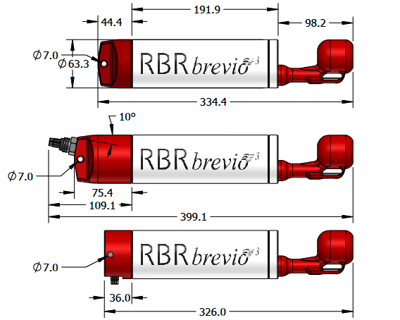
Fig. 7. RBRbrevio3 dimensions with three different battery end-caps
|
|
For deployment estimates specific for your instrument configuration and sampling options:
Note that deployment estimates are the same for shallow and deep variants. |
Power supply selection
If connected, an external power supply will be used preferentially over the internal batteries as long as the voltage remains 4.5V or greater. If it drops below 4.5V or complete disconnection occurs, the system automatically switches to the internal batteries.
Clock
The instrument clock is maintained during brief disconnections. This time is usually sufficient to change batteries. If the clock is lost, the time will revert to January 2000. In this case, check the power supply and synchronise with the computer again.
USB-C power
The USB-C cable provides power sufficient for configuration or data download. However, the instrument requires an internal or external power supply to perform sampling.
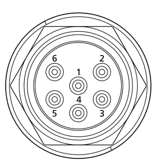
RBR standard instruments with connectorised battery end-caps (BEC12 and BEC13) have MCBH-6-MP connectors. These connectors facilitate communication out of the instrument to your computer via USB, RS-232, or RS-485 cables, depending on the wiring selected at the time of purchase.
External MCBH-6-MP connector pinout
|
Pin No. |
USB |
RS-232 |
RS-485 |
1 |
Ground |
|||
2 |
Power +4.5 to +30V |
|||
3 |
N/C |
From the |
From the |
|
4 |
+5V |
Into the |
Into the |
|
5 |
D- |
N/C |
Into the |
|
6 |
D+ |
N/C |
From the |
|
Additionally, the RBRconcerto³ variants with an elongated body and RBRmaestro³ instruments have MCBH-6-FS connectors.
|
RBR properly installs all sensors included with your instruments. The MCBH-6-FS pinouts (SV11 and serial) will only be needed when installing an additional sensor. If a spare connector may be required, it must be wired/activated at the time of purchase. |
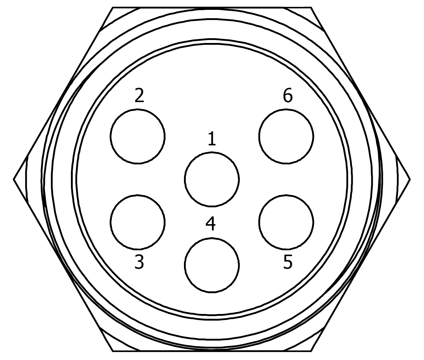
Use the MCBH-6-FS (SC11) connector to install raw voltage sensors (voltage kit, 0-5V general analogue input) and to communicate the data from these sensors to the instrument.
MCBH-6-FS (SC11) connector pinout
|
Pin No. |
Definition |
1 |
Power Ground |
|
2 |
Sensor signal (V) |
|
3 |
Sensor ground |
|
4 |
12V Sensor power |
|
5 |
N/C |
|
6 |
N/C |
Use the MCBH-6-FS (serial) connector to install RBR sensors with an RS-232 output and to communicate the data from these sensors to the instrument.
MCBH-6-FS (serial) connector pinout
|
Pin No. |
Definition |
1 |
Ground |
|
2 |
Sensor power |
|
3 |
Serial data output from the sensor |
|
4 |
Serial data input into the sensor |
|
5 |
N/C |
|
6 |
N/C |