Replace the O-rings
|
Refer to Open and close a compact instrument for details on accessing the O-rings. The O-ring removal tool and silicone compound are available in the support kit. |
Care for the O-rings is the single most important item of maintenance on any submersible RBR instrument. A water leak can damage the circuit board beyond repair and cause complete data loss. Every instrument seal depends upon the O-ring; therefore, proper O-ring maintenance is crucial.
|
The O-rings may lose elasticity over time, even when the instrument is not deployed. RBR strongly recommends replacing the O-rings regularly. |
RBR compact instruments use two O-rings (see Fig. 15). One is the main O-ring, and the other is the backup. Both are required to protect the instrument from flooding. To access the O-rings, open the instrument. |
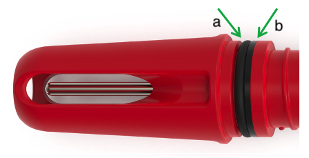
Fig. 15. Location of the O-rings. (a) main O-ring. (b) backup O-ring.
|
Inspecting the O-rings and mating surfaces
Visually inspect the O-rings and their mating surfaces, checking that each of the following is smooth and free of nicks or damage:
-
The surface of the O-ring itself
-
The mating surface on the inside of the case, between the threads and the open end
-
The groove in the end-cap where the O-ring sits
|
When handling the O-rings:
|
Replacing the O-rings
Correct placement and orientation of the two O-rings are critical to maintaining depth rating integrity.
The main O-ring has a round profile. It must be installed first.
The backup O-ring is flat on one side, and concave on the other. When installed, the concave side must face the main O-ring, as illustrated in Fig. 16. |
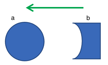
Fig. 16. Orientation of the O-rings (a) main O-ring. (b) backup O-ring.
|
Use the plastic O-ring tool (included with the support kit) to remove the O-rings from the groove. The O-ring may need to stretch quite a bit as it is pushed off; this requires some effort but can be done by hand.
-
Clean the groove thoroughly using a soft, lint-free cloth and compressed air if necessary.
-
Select the proper O-rings and inspect them for damage.
-
Lubricate with a very light film of silicone grease (included in the support kit).
-
Install the main O-ring by sliding it over the electronic housings and popping it into its groove.
-
Install the backup O-ring, ensuring that the concave side is facing toward the main O-ring.
-
Once in place, inspect the O-rings once more for scratches and debris, and wipe away any silicone compound deposited on the carriage.
-
Once the inspection is complete, close the instrument.