Antifouling
|
The RBRduo³ C.T | uv and RBRconcerto³ C.T.D | uv ship with the UV schedule disabled. See Ruskin User Guide: Standard Instruments³ for details on configuring the antifouling cycle. |
The RBRduo³ C.T | uv and RBRconcerto³ C.T.D | uv use ultraviolet radiation to reduce biofouling of the conductivity cell and thus improve accuracy of measurements during long-term deployments in epipelagic environment. Four UV LEDs installed on the inside of the guard illuminate critical sensor surfaces at one-minute intervals, slowing any biological growth.
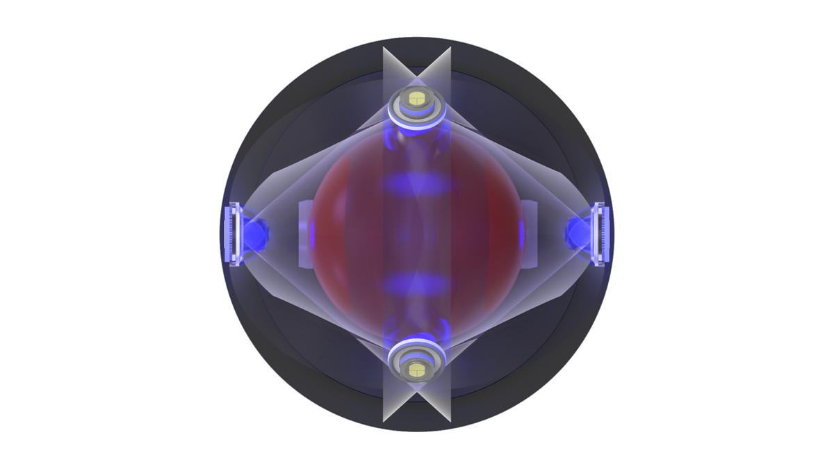
When active, the two upper UV LEDs emit ultraviolet radiation at the top sensor surfaces, while the two UV LEDs located on the spine of the guard illuminate the white ceramic tube inside of the CT cell where the bulk of the conductivity measurements occurs. As a result, the instruments with the active antifouling show a considerably lower salinity drift, compared with no-UV units.
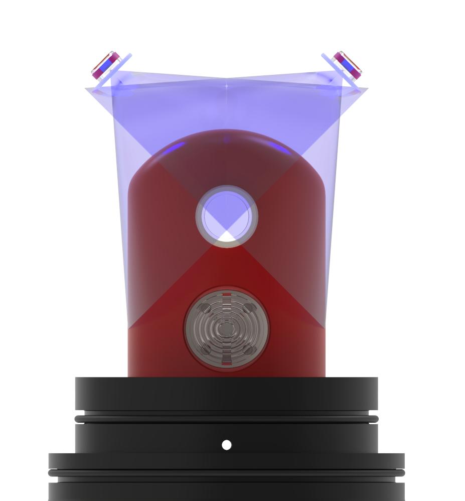
Fig. 2. Upper UV LEDs
|
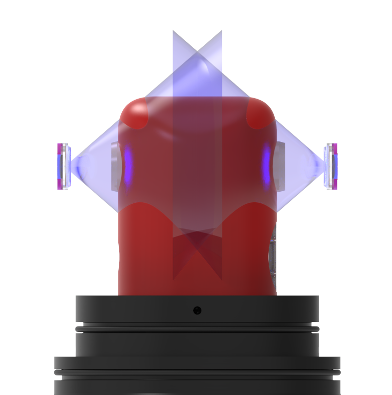
Fig. 3. UV LEDs located on the spine
|
|
The UV LEDs will activate immediately after you enable the deployment. See Safety precautions. |