mDP port: troubleshooting
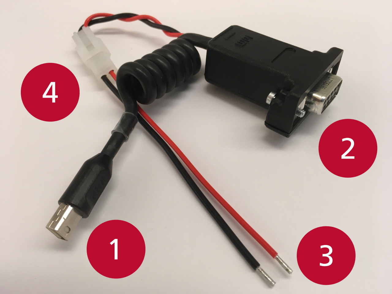
RBR Generation3 instruments and SSMs are equipped with an internal Mini DisplayPort (mDP) connector which carries serial data and power. The breakout adaptor (pictured right) enables diagnostic evaluation of the connector functionality.
Instrument
To test whether an instrument can receive power through the mDP port, provide power to the adaptor either via a power supply and the flying leads, or the RBRfermata-compatible connector. Then, to evaluate the state of power input, connect the instrument to Ruskin, either via RS-232 using the DE-9 connector on the adaptor, or via USB.
Adaptor

(1) The mDP connector carrying RS-232 data and power from the instrument or SSM.
(2) A DE-9 connector carrying RS-232 data to a computer.
(3) Power connectors (nominal 12V; 4-30V acceptable) as flying leads.
(4) RBRfermata battery pack (0002364/0002542) compatible power connector.
Provide power:
If the instrument is coupled to an SSM end-cap:
Open the instrument at the coupler.
Disconnect the umbilical cable between the SSM and instrument.
Connect the mDP connector (1) on the adaptor to the port on the instrument.
Provide power to the adaptor.
From a power supply:
If the supply output voltage is adjustable, set it to 12V. Otherwise, confirm with a multimeter/voltmeter that the output is in the 4-30V range.
Turn off the supply output.
Disconnect any other outputs from the supply.
Connect the positive terminal of your power supply to the red flying lead (3).
Connect the negative terminal of your power supply to the black flying lead (3).
Turn on the power supply.
From an RBRfermata battery pack:
On the adaptor, disconnect the flying leads (3) from the RBRfermata-compatible connector (4).
Measure and record the battery pack voltage with a multimeter/voltmeter.
Connect the power connector from the battery pack to the adaptor (4).
Connect to Ruskin.
Via an RS-232 serial port:
If you have a computer with an RS-232 serial port, connect the serial port of your computer to the DE-9 connector on the adaptor (2), directly or via a straight (non-null) extension cable.
Via USB:
Connect a USB-C cable from the computer to the USB-C port on the instrument. Leave the DE-9 connector on the adaptor (2) disconnected.
Never try to use USB and serial connection to the instrument simultaneously.
Verify power:
Open Ruskin on the computer. It should auto-detect the instrument and begin to communicate with it.
Open the “Information” tab. In the “Power” section, observe the external voltage.
The voltage displayed by Ruskin should be within 0.1V of the power supply or battery voltage.
If the measured voltage is close to your supply voltage but differs by more than 0.1V:
Check your connections.
Click the refresh button next to the voltage readings (cycling/circling green arrows) to update the displayed measurement.
If Ruskin cannot communicate with the instrument over the serial port, but can over USB, or if the external voltage reads 0.0V, then the mDP port on the instrument is likely faulty.
Please contact our service team to confirm the diagnosis and to arrange the return for service.
SSM
To test whether an SSM-equipped end-cap is forwarding external power, provide external power to the SSM either via a power supply and a patch cable with a power terminal block, or an RBRfermata. Then, to evaluate the state of power output, connect the adaptor to the mDP output of the SSM and measure the voltage across the flying leads.
Provide power:
When measuring the output voltage with a multimeter/voltmeter, use clip leads to connect to the flying leads on the adaptor. Don't hold probes to the leads with your fingers, or else you risk disturbing the measurement with static voltage.
If the SSM is coupled to an instrument:
Open the instrument at the coupler.
Disconnect the umbilical cable between the SSM and instrument.
Connect the mDP connector (1) on the adaptor to the port on the SSM.
Provide power to the SSM.
From a power supply:
If the supply output voltage is adjustable, set it to 12V. Otherwise, confirm with a multimeter/voltmeter that the output is in the 4-30V range.
Turn off the power supply.
Disconnect any other outputs from the supply.
Connect the positive terminal of your power supply to the positive terminal of the terminal block on the patch cable.
Connect the negative terminal of the power supply to the negative terminal of the terminal block on the patch cable.
Connect the MCIL-6-FS connector of the patch cable to the external power connector on the SSM.
From an RBRfermata:
Measure and record the RBRfermata voltage with a multimeter/voltmeter.
Connect the RBRfermata to the external power connector on the SSM.
Verify power:
Using a multimeter/voltmeter, measure the voltage across the flying leads of the adaptor (3).
The measured voltage should be within 0.1V of the power supply or battery voltage.
If the measured voltage is close to your supply voltage but differs by more than 0.1V:
Check your connections
Click the refresh button next to the voltage readings (cycling/circling green arrows) to update the displayed measurement.
If the measured voltage is 0.0V, then the mDP port on the SSM is likely faulty. Please contact our service team to confirm the diagnosis and to arrange a return for service.
