MLM troubleshooting
The RBRcervello uses the mooring line modem (“MLM”) inductive modem to communicate with the instrument mounted on the Wirewalker. The MLM system consists of a head-end modem (“HEM”) included within the buoy-mounted RBRcervello housing, and a sub-surface modem (“SSM”) coupled onto the Wirewalker-mounted instrument. The instrument mounted on the wirewalker needs to be configured to communicate at the baud rate as configured in the SSM which is typically 19200 bits-per-second.
The HEM offers diagnostic commands to assist in failure diagnosis. To open an interactive session with the HEM, connect to the debug port, then use the mlm command from the main RBRcervello debug menu:
Opening a connection to the MLM. Use ^D to quit.
The debug interface may indicate that the logger controller was stopped:
The logger controller is the component that continuously downloads data from the attached instrument. Because it uses the inductive modem to do this, it must be stopped before an interactive session with the modem can be opened.
MLM communication principles
Commands
Send each command to the modem on its own line. Lines must be terminated with a carriage return and/or a linefeed character. Most terminal emulators' default handling of the “<Enter>” key produces acceptable behaviour.
Sleep
If the modem receives no commands for 10 seconds, it will go to sleep. The modem will wake up when it next receives a line termination character. This can lead to the modem “ignoring” commands upon first connection, or after having sat idle. To ensure the modem evaluates your command, it is good practice to send a line termination (hit the “Enter” key) once or twice before each command to both wakes up the modem and to cause it to stay awake while you're typing.
The instrument also has a 10-second sleep timeout. When communicating with the instrument over the inductive modem link, the same technique of sending a line termination character before each command should also be followed. Moreover, there is a 10-second inactivity timeout for the modem connection to the instrument; if no data passes across the inductive modem link for ten seconds, the connection is closed. To avoid having to frequently reopen the channel, periodically send a line termination character.
Initial state
If the logger controller was running before the connection was opened, the MLM may still be in “transparent mode” – received commands will be passed directly to the attached instrument. To determine the state of the connection, send a line termination character once or twice to wake the HEM from sleep, then send the “a” command (by typing “a<Enter>”). The unit should respond:
Ready:
***command mode***
SSM discovery
The HEM can automatically discover connected SSMs. This is a straightforward, rapid way to verify basic MLM functionality. To invoke it, send the disc command to the HEM:
discovery requested
099999
discovery complete OK
- Type Ctrl+D to return to the debug menu.
- Use the
servicescommand to enter the services menu. - On the services menu, restart the logger controller service:
start loggercontroller. - Use the
exitcommand to exit to the debug menu. - Use the
exitcommand to close the debug interface.
Otherwise, continue on to checking the ferrites.
Checking the ferrites and coils
The “ferrite holders” (shown at right) hold the ferrite halves and clamp them to the mooring line. There is one underneath the buoy connected to the HEM, and one on the Wirewalker connected to the SSM. If either connection between ferrite and modem is faulty, the modem connection will be at best unreliable and at worst nonfunctional.
The ferrite holders are the first thing to check in the event that the HEM cannot see the SSM, starting with the surface ferrite holder. To perform a cursory check of the ferrite:
- Disconnect and reconnect the connectors at both ends of the cable to ensure that they are well-seated.
- Open the ferrite holder. Check visible edges of the ferrite for damage (scratches, chips). Wiggle/push the ferrite halves to confirm that they are intact, not cracked/split.
- Close the ferrite holder again, ensuring that the ends of both ferrite halves are flush and line up with each other.
If other tests point back to a ferrite failure, you can remove the ferrite halves from the enclosure to check them. Do this in a workshop or other safe area where any small pieces will not be lost during disassembly.
- Open the ferrite holder.
- Using a 3mm hex key, remove the retaining screws on the anti-strumming bar on the ferrite holder clasp. Remove the bar.
- Lift the ferrite half out of the recess, being careful to not lose the T-shaped spring from the bottom of the recess.
- Check the ferrite half for cracks or fractures. Check that the two O-rings are evenly spaced around it, approximately at thirds.
- Remove the spring from the recess. Make note of the orientation of the spring within the recess before removal: whether the top of the “T” is facing the left or right side of the clasp.
- Check the spring for cracks or surface scoring.
- Replace the spring. Replace the spring into the recess. Push the ferrite half back into the clasp. Replace the anti-strumming bar and tighten its retaining screws.
- Carefully slide the other ferrite half from the holder body and check it for cracks or fractures. Slide it back into its recess when satisfied.

Two ferrite holders, one with its clasp open.
The orientation of the spring determines the elevation it affords the ferrite half. If the ferrite halves do not compress tightly against each other when the clasp is closed, reorient the spring so the top of the “T” faces the clasp hinge.
Additionally, each ferrite holder contains a coil. With an ohmmeter, check the resistance across the outer two pins of the MC-BH-F connector on the ferrite holder. It should measure 3-4 Ω. Significantly more (hundreds of ohms or an open circuit) indicates a failure of the coil or the connector.
Checking the surface ferrite connection
In order to easily verify the connection, we will use the HEM to generate a constant tone, known as a “seize tone”. The seize tone will cause the ferrite to resonate at an audible frequency and is also observable as AC voltage across the pins of the ferrite connector.
To generate the constant seize tone, first issue the #rbr command to instruct the HEM to permit additional diagnostic commands:
commands now unlocked
commands now locked
Now issue the sz on command to begin generating the seize tone:
seize tone started
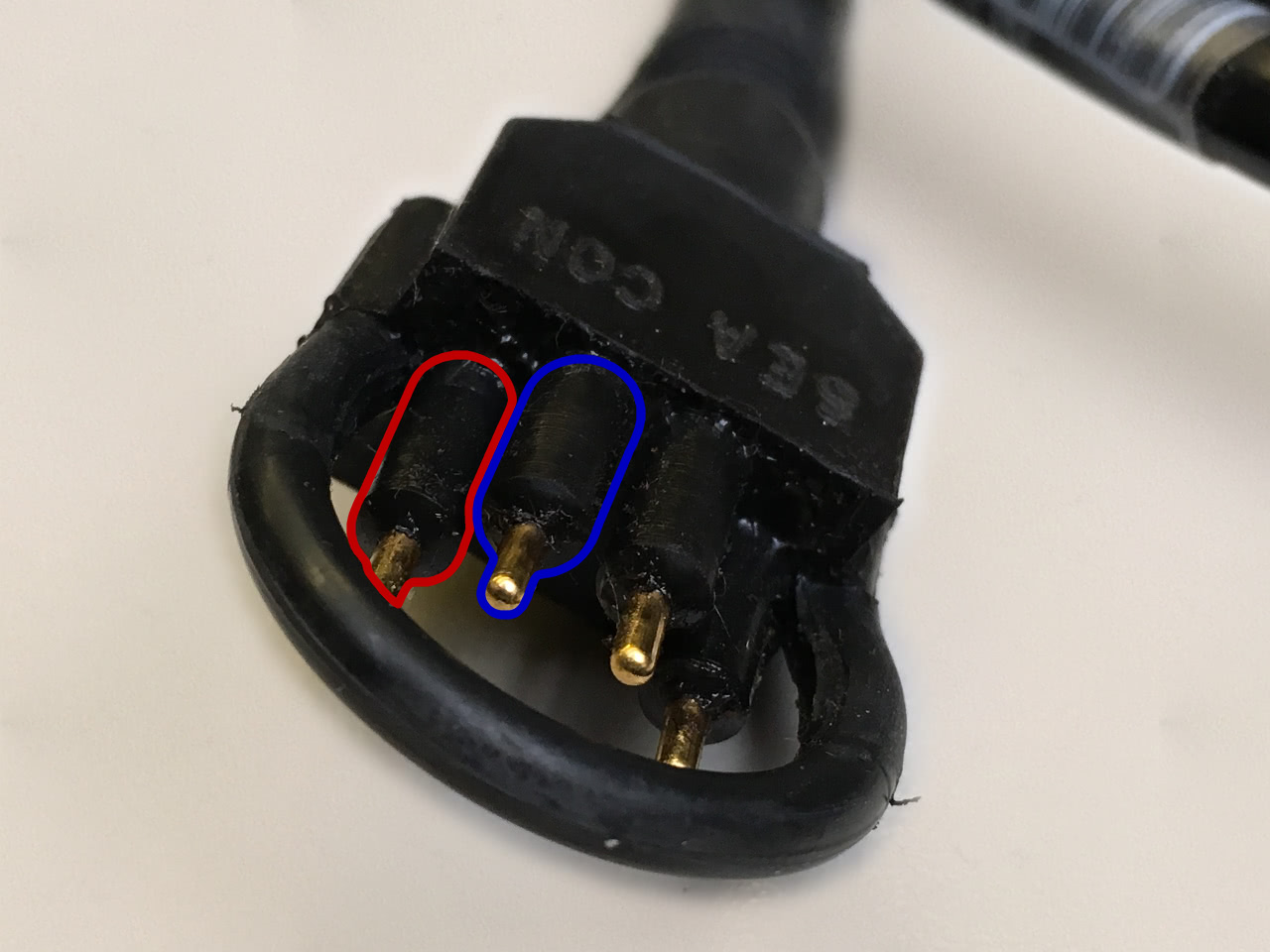
If you do not hear the tone, use a multimeter to check the cable for continuity. With the connectors oriented face-on and rotated so that the ends of the semicircular profiles formed by the pins face downward, and counting from the leftmost pin clockwise, check that the 1st pin of the 4-pin connector is continuous to the 3rd pin of the 3-pin connector and that the 2nd pin of the 4-pin connector is continuous to the 1st pin of the 3-pin connector. See the coloured outlines pictured.
If the connectors are continuous, test for AC voltage across the pins: first directly from the connector on the RBRcervello, then through the cable. While the seize tone is being produced, you should be able to measure approximately 2.8V AC across the pins.
- If the measured voltage is significantly different, please contact RBR.
- If you can measure the voltage on the RBRcervello connector but not on the other end of the cable, the cable is faulty.
- If you can measure the voltage on both ends of the cable but cannot hear a tone from the ferrite when connected, reopen the ferrite holder and recheck both ferrite halves as described above.
When using a direct-connect HEM, which connects inline with the inductive loop and does not use a ferrite holder, the expected voltage across the pins is 3.0V AC.
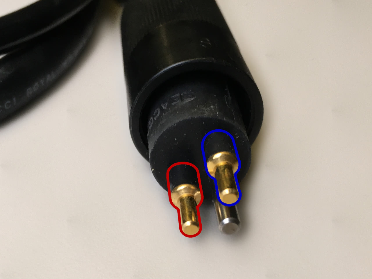
Top: the ferrite holder cable, RBRcervello end
Bottom: the ferrite holder cable, ferrite holder end
To cease seize tone generation, use the sz off command:
seize tone stopped
Checking the sub-surface ferrite connection
Perform the same basic checks described above: check the cabling between the modem and the ferrite holder; open the holder and check the ferrite itself; and close the holder, checking that the ferrite halves mate well.
To cause a constant stream of communication attempts across the inductive link, we will restart the logger controller. First, we will enable logging for the service so we can monitor its status.
- At the
debug>prompt, enter thelogscommand to enter the logs menu. - At the
debug\logs>prompt, enterenable loggercontrollerto enable logging for the logger controller service. - Enter
exitto return to the debug menu. - At the
debug>prompt, enter theservicescommand to enter the services menu. - At the
debug\services>prompt, enterstart loggercontrollerto start the logger controller service. - Enter
exitto return to the debug menu. - At the
debug>prompt, enter thelogscommand to enter the logs menu again. - Enter
show /mnt/sdcard/logs/loggercontroller.logto show the logs for the logger controller service.
The pager used to show log files is GNU less.
- To scroll up and down through the file, use the arrow keys.
- To jump to the end of the file, type Shift+G.
- To watch the end of the file (wait for new data to appear), type Shift+F.
- While watching the end of the file, type Ctrl+C to return to scrolling mode.
- To quit to the logs menu, type Q.
To use the log file output to confirm a connection between the RBRcervello and instrument over the inductive modem:
- Type Shift+F to begin watching the end of the file.
- Connect the HEM to the SSM by closing both ferrite holders around the test loop.
- Optical sensors on the instrument should light up. After ten or twenty seconds of exchanging commands with the instrument (visible in the log output), the logger controller log output should indicate that it is downloading from the instrument.
When finished:
- Type Q to close the log file.
- Enter
exitto return to the debug menu. - Enter
exitto close the debug interface.